RS-232 (DB9)

RS-232 (DB9)

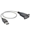
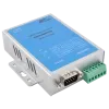
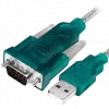
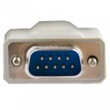
In telecommunications, RS-232 (Recommended Standard 232) is a standard for serial binary data signals connecting between a DTE (Data Terminal Equipment) and a DCE (Data Circuit-terminating Equipment). It is commonly used in computer serial ports. A similar ITU-T standard is V.24.

The Electronics Industries Association (EIA) standard RS-232-C as of 1969 defines:

  • Electrical signal characteristics such as voltage levels, signaling rate, timing and slew-rate of signals, voltage withstand level, short-circuit behavior, and maximum load capacitance.
  • Interface mechanical characteristics, pluggable connectors and pin identification.
  • Functions of each circuit in the interface connector.
  • Standard subsets of interface circuits for selected telecom applications.

The standard does not define such elements as

  • character encoding (for example, ASCII, Baudot code or EBCDIC)
  • the framing of characters in the data stream (bits per character, start/stop bits, parity)
  • protocols for error detection or algorithms for data compression
  • bit rates for transmission, although the standard says it is intended for bit rates lower than 20,000 bits per second. Many modern devices support speeds of 115,200 bit/s and above
  • power supply to external devices.

Details of character format and transmission bit rate are controlled by the serial port hardware, often a single integrated circuit called a UART that converts data from parallel to asynchronous start-stop serial form. Details of voltage levels, slew rate, and short-circuit behavior are typically controlled by a line-driver that converts from the UART's logic levels to RS-232 compatible signal levels, and a receiver that converts from RS-232 compatible signal levels to the UART's logic levels.

The original DTEs were electromechanical teletypewriters and the original DCEs were (usually) modems. When electronic terminals (smart and dumb) began to be used, they were often designed to be interchangeable with teletypes, and so supported RS-232. The C revision of the standard was issued in 1969 in part to accommodate the electrical characteristics of these devices.

Since application to devices such as computers, printers, test instruments, and so on was not considered by the standard, designers implementing an RS-232 compatible interface on their equipment often interpreted the requirements idiosyncratically. Common problems were non-standard pin assignment of circuits on connectors, and incorrect or missing control signals. The lack of adherence to the standards produced a thriving industry of breakout boxes, patch boxes, test equipment, books, and other aids for the connection of disparate equipment. A common deviation from the standard was to drive the signals at a reduced voltage: the standard requires the transmitter to use +12V and -12V, but requires the receiver to distinguish voltages as low as +3V and -3V. Some manufacturers therefore built transmitters that supplied +5V and -5V and labeled them as "RS-232 compatible."

Later personal computers (and other devices) started to make use of the standard so that they could connect to existing equipment. For many years, an RS-232-compatible port was a standard feature for serial communications, such as modem connections, on many computers. It remained in widespread use into the late 1990s. While it has largely been supplanted by other interface standards, such as USB, in computer products, it is still used to connect older designs of peripherals, industrial equipment (such as based on PLCs), and console ports, and special purpose equipment such as a cash drawer for a cash register.

The standard has been renamed several times during its history as the sponsoring organization changed its name, and has been variously known as EIA RS-232, EIA 232, and most recently as TIA 232. The standard continued to be revised and updated by the Electronic Industries Alliance and since 1988 by the Telecommunications Industry Association (TIA). Revision C was issued in a document dated August 1969. Revision D was issued in 1986. The current revision is TIA-232-F Interface Between Data Terminal Equipment and Data Circuit-Terminating Equipment Employing Serial Binary Data Interchange, issued in 1997. Changes since Revision C have been in timing and details intended to improve harmonization with the CCITT standard V.24, but equipment built to the current standard will interoperate with older versions.

RS-232 devices may be classified as Data Terminal Equipment (DTE) or Data Communications Equipment (DCE); this defines at each device which wires will be sending and receiving each signal. The standard recommended but did not make mandatory the D-subminiature 25 pin connector. In general and according to the standard, terminals and computers have male connectors with DTE pin functions, and modems have female connectors with DCE pin functions. Other devices may have any combination of connector gender and pin definitions. Many terminals were manufactured with female terminals but were sold with a cable with male connectors at each end; the terminal with its cable satisfied the recommendations in the standard.

Presence of a 25 pin D-sub connector does not necessarily indicate an RS-232-C compliant interface. For example, on the original IBM PC, a male D-sub was an RS-232-C DTE port (with a non-standard current loop interface on reserved pins), but the female D-sub connector was used for a parallel Centronics printer port. Some personal computers put non-standard voltages or signals on some pins of their serial ports.

The standard specifies 20 different signal connections. Since most devices use only a few signals, smaller connectors can often be used. For example, the 9 pin DE-9 connector was used by most IBM-compatible PCs since the IBM PC AT, and has been standardized as TIA-574. More recently, modular connectors have been used. Most common are 8P8C connectors. Standard EIA/TIA 561 specifies a pin assignment, but the "Yost Serial Device Wiring Standard" invented by Dave Yost (and popularized by the Unix System Administration Handbook) is common on Unix computers and newer devices from Cisco Systems. Many devices don't use either of these standards. 10P10C connectors can be found on some devices as well. Digital Equipment Corporation defined their own DECconnect connection system which was based on the Modified Modular Jack connector. This is a 6 pin modular jack where the key is offset from the center position. As with the Yost standard, DECconnect uses a symmetrical pin layout which enables the direct connection between two DTEs. Another common connector is the DH10 header connector common on motherboards and add-in cards which is usually converted via a cable to the more standard 9 pin DE-9 connector (and frequently mounted on a free slot plate or other part of the housing).