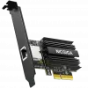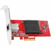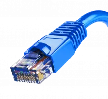
The 8P8C (8 Position 8 Contact, also acronym as 8 position 8 conductor; often called RJ45) is a modular connector commonly used to terminate twisted pair and multiconductor flat cable. These connectors are commonly used for Ethernet over twisted pair, registered jacks and other telephone applications, RS-232 serial using the EIA/TIA 561 and Yost standards, and other applications involving unshielded twisted pair, shielded twisted pair, and multi-conductor flat cable.
An 8P8C modular connector has two paired components: the male plug and the female jack, each with eight equally-spaced conducting channels. On the plug, these conductors are flat contacts positioned parallel with the connector body. Inside the jack, the conductors are suspended diagonally toward the insertion interface. When an 8P8C plug is mated with an 8P8C jack, the conductors meet and create an electrical connection. Spring tension in the jack's conductors ensure a good interface with the plug and allow for slight travel during insertion and removal.
Although commonly referred to as an RJ45 in the context of Ethernet and category 5 cables, it is technically incorrect to refer to a generic 8P8C connector as an RJ45. The registered jack (RJ) standard specifies a different mechanical interface and wiring scheme for a true RJ45 than TIA/EIA-568-B which is often used for modular connectors used in Ethernet and telephone applications. 8P8C modular plugs and jacks look very similar to the plugs and jacks used for FCC's registered jack RJ45 variants, although the true RJ45 is not compatible with 8P8C modular connectors.
"RJ45" naming confusion
RJ45 was originally a telephone-only standard. It is one of the many registered jacks, like RJ11, another telephone standard. As a registered jack, telephone RJ45 specifies the physical male and female connectors as well as the pin assignments of the wires in a telephone cable. The original RJ45 uses a special keyed 8P2C modular connector, with Pins 5 and 4 wired for tip and ring of a single telephone line and Pins 7 and 8 connected to a programming resistor. It is meant to be used with a high speed modem, and is obsolete today.
Telephone installers who wired telephone RJ45 jacks were familiar with the pin assignment which was part of the RJ45 standard. However, near-identical physical connectors for computer networking became ubiquitous, and informally inherited the name RJ45 due to the overwhelming similarity. While telephone RJ45 uses a "keyed" variety of the 8P body, meaning it may have an extra tab that a computer RJ45 connector is unable to mate with, the visual difference from an Ethernet 8P is subtle.
The only other difference is the presence of extra conductors in the cable, which cannot be seen without very close inspection. True telephone RJ45 connectors are a special variant of 8P2C, meaning only the middle 2 positions have conductors in them, while pins 7 and 8 are shorting a programming resistor. Computer RJ45 is 8P8C, with all eight conductors present.
Understandably, because telephone RJ45 8P connectors never saw wide usage and computer 8P connectors are quite well known today, RJ45 is used almost exclusively to refer to Ethernet-type computer connectors. Electronics catalogs not specialized to the telephone industry advertise 8P8C modular connectors as "RJ45". Virtually all electronic equipment that uses an 8P8C connector (or possibly any 8P connector at all) will document it as an "RJ45" connector. In common usage, RJ45 also refers to the pin assignments for the attached cable, which are actually defined in the wiring standard TIA/EIA-568-B.
Standardization
The shape and dimensions of an 8P8C modular connector are specified for U.S. telephone applications by the Administrative Council for Terminal Attachment (ACTA) in national standard ANSI/TIA-1096-A. This standard does not use the short term 8P8C and covers more than just 8P8C modular connectors, but the 8P8C modular connector type is the eight position connector type described therein, with eight conductors installed.
For data communication applications (LAN, structured cabling), International Standard IEC 60603 specifies in parts 7-1, 7-2, 7-4, 7-5, and 7-7 not only the same physical dimensions, but also high-frequency performance requirements for shielded and unshielded versions of this connector for frequencies up to 100, 250 and 600 MHz, respectively.
Wiring
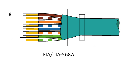
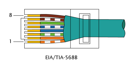
Connectors are frequently terminated using the T568A or T568B pin/pair assignments that are defined in TIA/EIA-568-B. A cable that is wired as T568A at one end and T568B at the other (Tx and Rx pairs reversed) is a "crossover" cable. Before the widespread acceptance of auto-MDI/MDIX capabilities a crossover cable was needed to interconnect similar network equipment (such as hubs to hubs). Crossover cables are still used today to connect two computers together without a switch or hub. A cable wired the same at both ends is called a "patch" or "straight-through" cable, because no pin/pair assignments are swapped.
Types
Two types of 8P8C plugs and installation tools (used for crimping the plug onto a cable) are commonly available: Western Electric/Stewart Stamping (WE/SS) and Tyco/AMP. While both types look remarkably similar, the tooling used to install the two different plug types is mutually exclusive and cannot be interchanged between the two types. WE/SS compatible plugs are available from a large number of manufacturers, whereas Tyco/AMP plugs are produced exclusively by Tyco Electronics. Both types of modular plugs will plug into the same standard 8P8C modular jack.
WE/SS and Tyco/AMP 8P8C plugs have different spacing for the cable strain relief. As a result, using a WE/SS 8P8C crimp dieset on a Tyco/AMP 8P8C plug will crush the top of the connector, and vice versa. While the WE/SS compatible plug is produced by a larger number of manufacturers than the Tyco/AMP plug, it is still important to know what style is being used to avoid damaging the plug during crimping.
Both types of 8P8C plugs are available in shielded and unshielded varieties, depending on the attenuation tolerance needed. Shielded plugs are more expensive and require shielded cable, but have a lower attenuation and can reduce signal noise.
Termination
Termination of a cable with an 8P8C plug involves using a hand crimper or crimp machine containing an 8P8C die-set or an A67T standard die-set. An 8P8C crimp die-set usually looks similar to an 8P8C jack, except for the eight teeth lining the top portion of the die. When the tool is operated, the die compresses around the 8P8C plug. As the die compresses, these teeth force the plug contacts down into the conductors of the cable being terminated, permanently attaching the plug to the cable. There are two sub-types of plug, that differ only in the type of contacts used. One contact suits solid copper cable and the other suits stranded copper cable. The crimper may also permanently deform part of the plug body in such a way that it grips the outer sheath of the cable. This helps to keep the plug securely fastened to the end of the cable, by providing strain relief.
Applications
8P8C are commonly used in computer networking and telephone applications, where the plug on each end is an 8P8C modular plug wired according to a TIA/EIA standard. Most network communications today are carried over Category 5e or Category 6 cable with an 8P8C modular plug crimped on each end.
The 8P8C modular connector is also used for RS-232 serial interfaces according to the EIA/TIA-561 standard. This application is commonly used as a console interface on network equipment such as switches and routers. Other applications include other networking services such as ISDN and T1.
In floodwired environments the center (blue) pair is often used to carry telephony signals. Where so wired, the physical layout of the 8P8C modular jack allows for the insertion of an RJ11 plug in the center of the jack, provided the RJ11 plug is wired in true compliance with the U.S. telephony standards (RJ11) using the center pair. The formal approach to connect telephony equipment is the insertion of a type-approved converter.
The remaining (brown) pair is increasingly used for Power over Ethernet (PoE). Legacy equipment may use just this pair; this conflicts with other equipment as manufacturers used to short circuit unused pairs to reduce signal crosstalk. Some routers/bridges/switches can be powered by the unused 4 lines—blues (+) and browns (−)—to carry current to the unit. There is now a standardized scheme for Power over Ethernet]
Different manufacturers of 8P8C modular jacks arrange for the pins of the 8P8C modular connector jack to be linked to wire connectors (often IDC type terminals) that are in a different physical arrangement from that of other manufacturers: Thus, for example, if a technician is in the habit of connecting the white/orange wire to the "bottom right hand" IDC terminal, which links it to 8P8C modular connector pin 1, in jacks made by other manufacturers this terminal may instead connect to 8P8C modular connector pin 2 (or any other pin).